This system is an intelligent local controller for a group of power supplies. It will conform to the JCOP model for HV control in that it will act as a master on the external communications path to send severe alarm messages and out of tolerance alerts. Also, the command repertoire will be a subset of the JCOP command set. Password protected internet access is foreseen. All commands and data values will be checked for validity before being transmitted to the supplies. Loading and retrieving informati on from the supplies is via a fieldbus network.
This system is a basic one for majority of subdetectors. It is therefore not surprising that there is a comon effort to develop control software for it. The system is (at the end of 2000) already well advanced and the first applications for HCAL specific hardware will follow shortly.
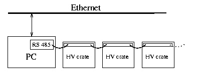
Left-right separation of the HV control with two PCs as controllers is foreseen. The chosen serial interface is RS 485 whose address space allows 255 crates. Exact number of needed crates and PCs will have to be re-checked, as well as the bandwidth of the connection.
For HV each module there is a number of parameters to occasionally set such as the trip values, the set values, the ramp speeds, etc. For real time monitoring we will need the current and voltage readback for five channels of HV, five chanels of bias voltage and the status word. Therefore, there are max 21 values polled per module in a single cycle. With six modules per crate it gives 126 values per crate.
Needs: driver, custom software (that downloads the crate parameters through the crate controllers, polls the crates and does the initial processing of data) and "a piece of SCADA" that has at least Event and DB managers. DB is needed for storing the preset and current values. Advantage: reduce the network traffic and ensure autonomy of the system. Graphical user interface can be run either locally or centrally by CMS SCADA partitioning. By using SCADA we avoid the need to have GUI written as a part of custom software.
It is also foreseen to have an EPROM for storing the default values in the controller itself.
Approach used by CAEN for LHC-like HV control is presented in Fig. 1.
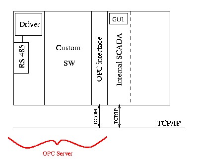
This approach, although reasonable for a big company is not appropriate for a single, well defined, custom made system. Writing the HV driver, custom software and OPC interface to conform to the standards and rules of an OPC Server are complex and time and effort consuming tasks. As the additional inconvenience, the OPC interface is hooked to DCOM protocol which makes any direct access from UNIX computers impossible.
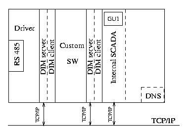
The proposed solution is the use of DIM server/client buffers for decoupling elements. As they are accessible through TCP/IP they enable not only modularity of the software, but also low-level debugging in case of trouble with SCADA. The point to keep in mind is to have access to DIM servers blocked while SCADA is running - it is unwise to have somebody play with HV during run.
Distributed Information Management System (DIM) is used to provide the inter-process communication. It is a package developed at CERN, used by several experiments (L3, DELPHI) and is fully approved and supported by CERN/JCOP.
The block diagram of such a system is shown in Fig. 2.
This approach is already used by CMS ME1/1 group and followed by the HCAL Sofia team which is developing hardware. Their driver and the software are written in Borland DELPHI language, which has very rich libraries. The used version is object oriented Pascal which can be automatically translated to Borland C++. The use of commercial software was not considered to be a problem as with any C++ code the change of compiler usually encompasses a long period of recovery. The final result is executable code completely independent of any vendor.